company number 8505715

Tank Farm Cathodic Protection
These are notes made relating to a report of an impressed current cathodic protection system that has been refurbished due to the design date expiring.
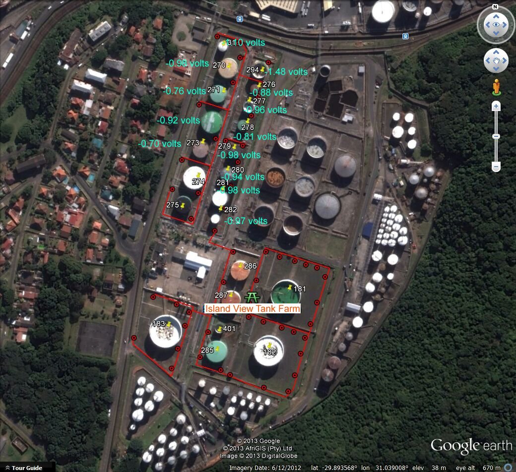
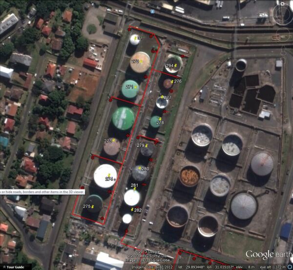
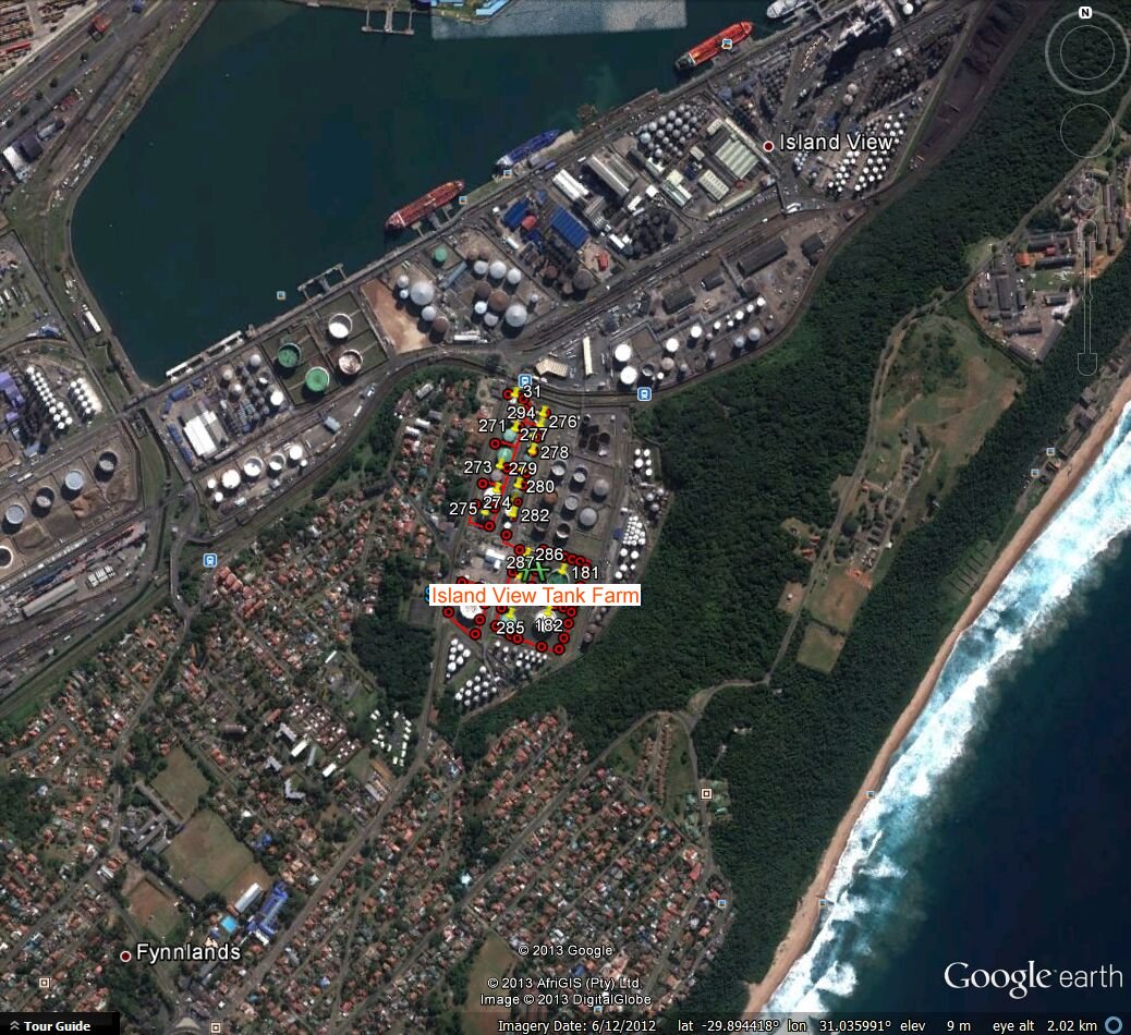
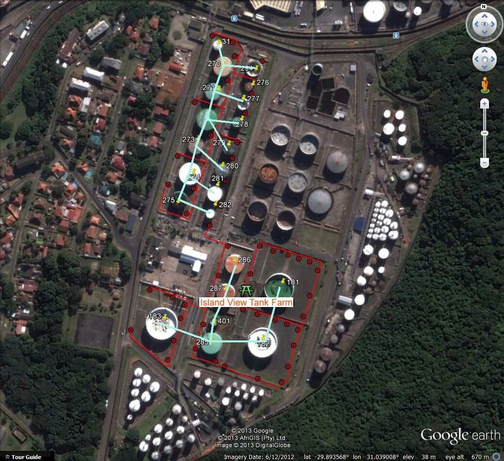
This is a satellite view of the tank farm
EXECUTIVE SUMMARY
INTRODUCTION
It can be seen that the tank farm is a mass of connected metal in contact with the ground and that this should be regarded as ay other electrical circuit for the purposes of electrochemical analysis. Electrical charges are generated at TRU's that can be likened to battery chargers or laptop computer power supplies. It can be seen that the charges are impressed into the ground through cables from the positive terminal of each TRU and these charges take the least line of resistance to complete their sircuit to the negative terminal, that is directly connecte to the metal mass of the tanks, pipes and facilities. The red markings show the cable runs and the red circles show the positions of the anodes through which the charges pass to remote earth.
Island View tank farm Cathodic protection was designed and installed by OICCG and had reached its design life span. I.E.S was then mandated to remove and installed all 52 anodes located around the tank farm and then replace two old 3-phase, tap-changed units with automated units located in the IVB old substation. The evaluation and design of the IVB CP system was not part of IES scope however would make recommendation to ENGEN on their findings.
In order to design and determine the required CP levels certain critical aspect needs to be known i.e.:Tank design Construction history (construction dates, soil resistivity, design life, repairs, corrosion history ect.) Type of service (stored product, Product temperature ect.) Foreign buried structures and Cathodic protection in the vicinity Stray current and maintenance records should be part of the investigation.
All data should be evaluated and processed thereafter it would be required to ground truth factual accuracy of the data.
I fact it has proved impossible to obtain and examine any documantation or to gain knowledge of any of the above points with the exception of that described below.
The main aim is to provide adequate structure protection however there is no historical data to prove that the initial/current system did/does indeed meet minimum criterion hence the design does not comply with current standards of testing ie no Permanent Reference Electrode and coupon installed to undertake the tests.
OBJECTIVE
The primary objective of this project was to replace depleted anode ground bed and replacement of the two old Transformer Rectifier Units with new Transformer Rectifier Units. because the current system had exceeded its life span.
The secondary objective was to commission the system and evaluate the effectiveness of the CP system installed, in the interim provide sound engineering interventions/ recommendation to economically rectify non complying standards to more recent ones.
METHOD
Two Transformer Rectifier Units identified as IVBA and IVBB supplied anodes on the South side and the North side of the Tank farm respectively.
Anodes were disconnected from the supply to allow for disconnection and removal of old anodes.
Excavation was done to remove buried anodes and install new anodes vertically in the ground using a manual hand auger to the depth of 3m deep. Old anodes were predominately depleted in almost all instances.
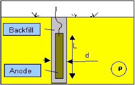
Upon removal the anodes were replaced with the new MMO inserted vertically in the augured hole and covered with conductive material “cor carb” (refer to figure 1),
A 10m cable tail was brought to a junction box via PVC conduit to connect to the ring main.
Single anode vertical installation
Cables and conduits were repaired or replaced where applicable. After the anodes had been installed the old Transformer Rectifier Units were removed and replaced with the new automated plc controlled units.
The table below shows the voltage measurements that were taken at various locations as found , then with the old system switched off and then after completion of our work.
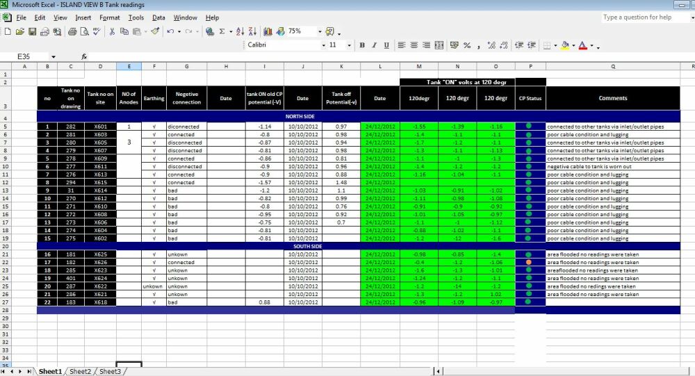
The pictures below show these measurements for easy analysis.
switched off readings from old records
switched on readings from old records

switched on readings after refurbishment

UNIT
DESIGN CAPACITY 76 Volts
ACTUAL 51.5 volts
COMMENTS
Unit Excessively Hot
TRU running at max capacity
Depleted Groundbed
DIAGNOSIS
TRU DRIVING FORCE Volts 76 51.5
TRU CURRENT Amperes 50 1.5
Low. Insufficient current for protection Depleted Groundbed
TRU AVAILABILITY % 100 100
TRU UTILISATION % 100 100
DRAIN POINT POTENTIAL Volts N/A -1.80
Drain point potential too low to ensure protection at points further away from TRU Lowered based on Petronas concern about Cathodic Disbonding
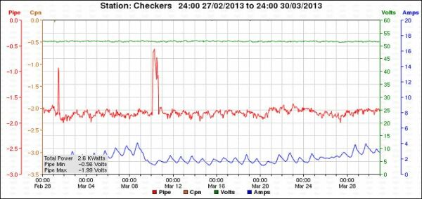
Recommendations:Replace Checkers TRU : New units to be an automatic, rapid response controlled unit, PLC controlled, Replace Anode Groundbed : o Both these actions would result in the TRU supplying sufficient current for corrosion protection as well as being able to more rapidly respond to mitigating any stray current Upgrade RMU software : New software Replace TRU enclosure : with ROCLA enclosure
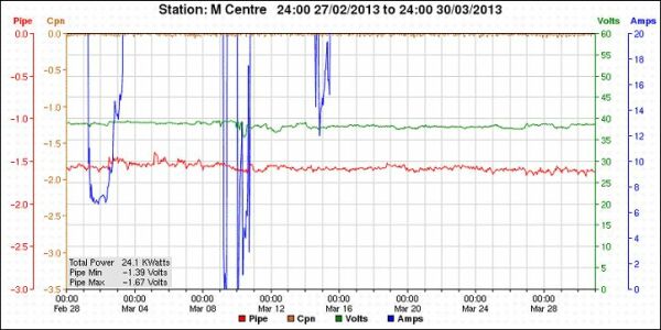
Figure 2: Medical Centre – March2013
UNIT DESIGN CAPACITY ACTUAL COMMENTS DIAGNOSIS
TRU DRIVING FORCE Volts 75 38.0
Operating at 51 % of its capacity
TRU CURRENT Amperes 50 27.0
Excessive current oscillation Stray current
TRU AVAILABILITY % 100 100
TRU UTILISATION % 100 100
DRAIN POINT POTENTIAL Volts -1.54
Pipe potential above minimum required criteria
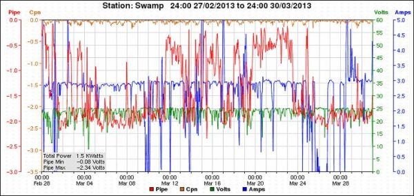
Recommendations: • Excessive current excursions suggestive of extreme stray current activity. • Investigation into the reasons for the TRU current excursions , • Investigation into the source of stray currents in this area, • Develop mitigation plans for the stray current problem UNIT DESIGN CAPACITY ACTUAL COMMENTS DIAGNOSIS TRU DRIVING FORCE Volts 70 14.6 TRU is unable to control voltage and current output Ineffective TRU TRU CURRENT Amperes 50 2.7 TRU is unable to control voltage and current output Groundbed depleted TRU AVAILABILITY % 100 100 TRU UTILISATION % 100 100 DRAIN POINT POTENTIAL Volts -1.07 CP System often falls below min required volts criteria stray current interference
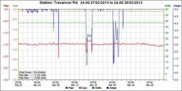
Observations: • Significant presence of stray current in the Swamp region • The current TRU is incapable of reacting timeously to mitigate the stray current (quantum and frequency). • As a result, the pipeline potentials regularly fall below the required protection levels. • This section of pipeline is seriously compromised and will remain so unless drastic mitigation actions are taken. • Analogy Voltmeter is faulty Recommendations: • Replace the SWAMP TRU with an automatic rapid response controlled unit, preferably PLC controlled, • RMU software upgrade and back up battery replacement • Voltmeter should be replaced UNIT DESIGN CAPACITY ACTUAL COMMENTS DIAGNOSIS TRU DRIVING FORCE Volts 76 48.3 TRU CURRENT Amperes 50 5.1 Insufficient current output to protect pipeline Ineffective Groundbed TRU AVAILABILITY % 100 100 TRU UTILISATION % 100 100 DRAIN POINT POTENTIAL Volts -1.47 Pipe potential above minimum required criteria
Observations:
Recommendations: • Replace Anode Groundbed , • More investigation is required about the pipe connection and crossbonds
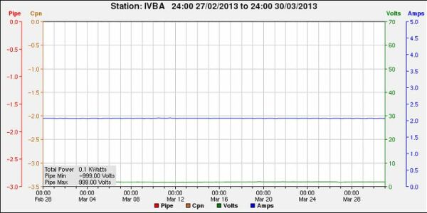
Figure 5: Island view BA: March 2013
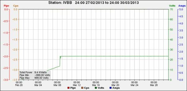
UNIT DESIGN CAPACITY ACTUAL Measured COMMENTS DIAGNOSIS TRU DRIVING FORCE Volts 75 2.0 Low Volts Ineffective Groundbed TRU CURRENT Amperes 50 2.1 Low Amps Ineffective Groundbed TRU AVAILABILITY % 100 100 TRU UTILISATION % 100 100 DRAIN POINT POTENTIAL Volts N/A Cable to tank connections not confirmed Poor Design
Recommendations:
• Install new Shell approved reference electrodes for refinery use at close to tank, • Install new Cable to tank connections, • RMU : Upgrade software,
Figure 6: Island view BB : March 2013
UNIT DESIGN CAPACITY ACTUAL Measured COMMENTS DIAGNOSIS TRU DRIVING FORCE Volts 75 23.4 System balanced TRU CURRENT Amperes 50 16.7 System balanced TRU AVAILABILITY % 100 100 TRU UTILISATION % 100 100 DRAIN POINT POTENTIAL Volts N/A Cable to tank connections not confirmed Poor Design
Recommendations: • Install new Shell approved reference electrodes for refinery use at close to tank, • Install new Cable to tank connections, • RMU : Upgrade RMU software, • RMU : Replace backup battery
Figure 6: Island View C : March 2013
UNIT DESIGN CAPACITY ACTUAL Measured COMMENTS DIAGNOSIS TRU DRIVING FORCE Volts 70 26.9 Operating at 30% of its maximum capacity TRU CURRENT Amperes 30 38.6 TRU AVAILABILITY % 100 100 TRU UTILISATION % 100 100 DRAIN POINT POTENTIAL Volts N/A Cable to tank connections not confirmed Poor Design
Recommendations: • Cable to tank connections to be re-established • Install new Shell approved reference electrodes for refinery use close to tank,
Figure 7: Spot Potentials from TP10 to Island View
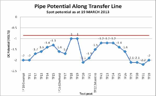
Observations: • Observations were made based on the spot “on” potentials • Transfer line predominantly protected according to on potentials, but need to be confirmed via off potential readings, • Test post 18 and 19 is still an area of concern, when compared to previous data polarization and depolarization is evident from each site visit.
Recommendations: • Test posts to be retrofitted to be able to conduct effective “off” potential readings at each test post location, • Off potentials the only true way to determine CP effectiveness • Investigation into root cause for the rapid current consumption between test posts 18 and 19 to be done and suitable actions implemented to correct this should be initiated
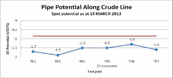
Figure 8: Spot Potentials from TP1 to TP7
Comments based on Cathodic Protection Network International Limited Technology
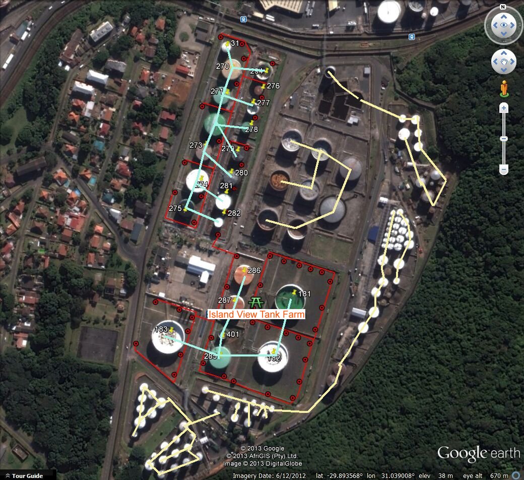
This picture shows the 'metalic block'of all the welded and directly connected metal in the whole area but it is not clear if other metal structures and tanks are in direct electrical contact with the negative connection of our TRU's.
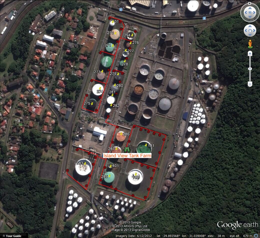
The North section of the tank farm is alongside other tanks that will be in the area of influence of our anodes and will be positively charged if not connected directly to the negative of our TRU's
The blue lines show the negative part of the circuit and the yellow lines show the metal that will have been charged positive. The red arrows show the direction through the ground that the charges will tend to travel.
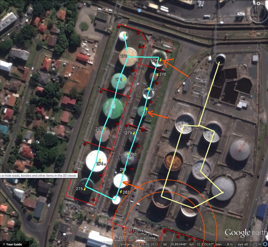
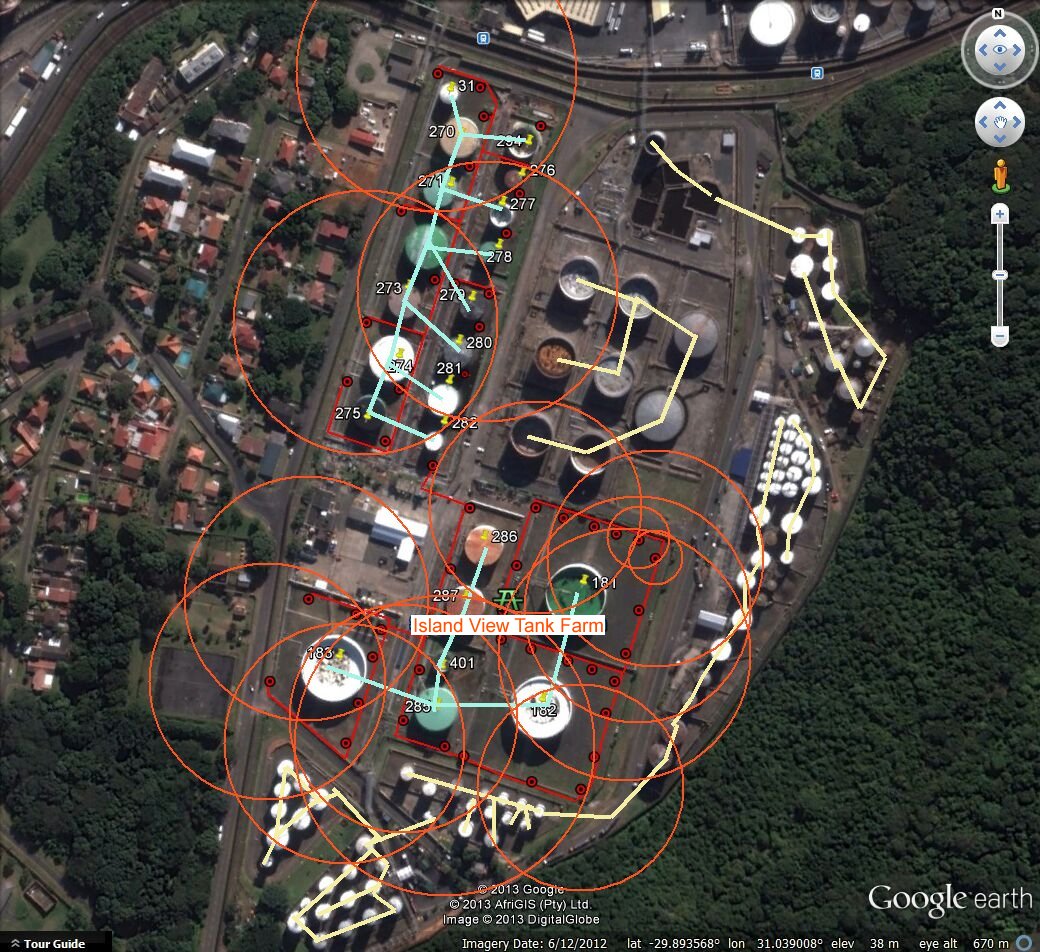
The charges from the South side of the circuit are travelling to remote earth through the least line of resistance as all grounded charges follow a path determined by the inverse square law of radiation, but including variations caused by differing resistanced in the composition of the material that constitutes the ground.
The red circles show the plan view of the hemisphers of resistancefrom the anodes to remote earth and how they overlap the tanks that they are designed to protect AND adjacent tanks and facilities. The blue lines show the negative return path of the charges and the red arrows show the possibe earth path through the ground of the 'stray current' caused by our own system.
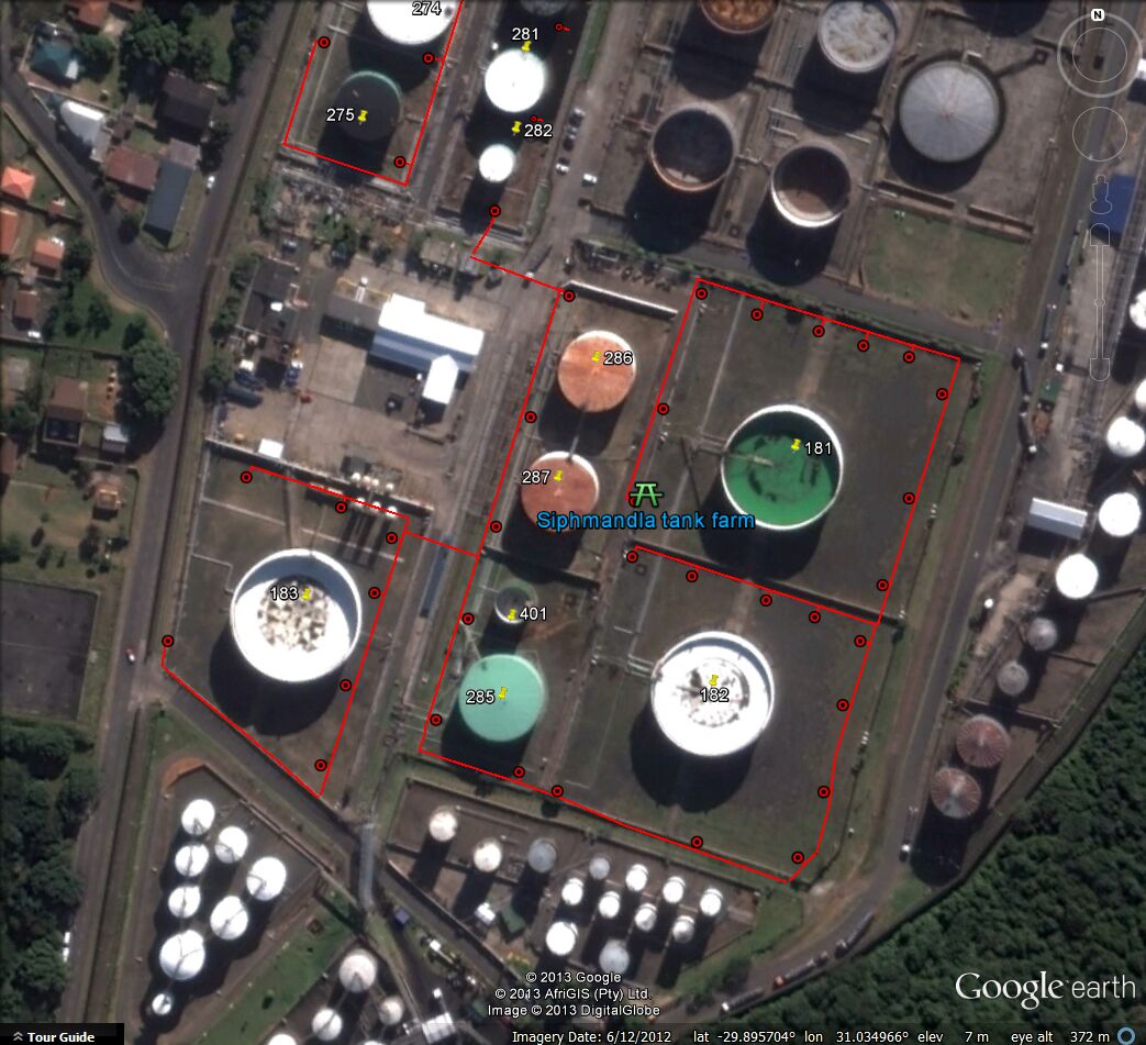
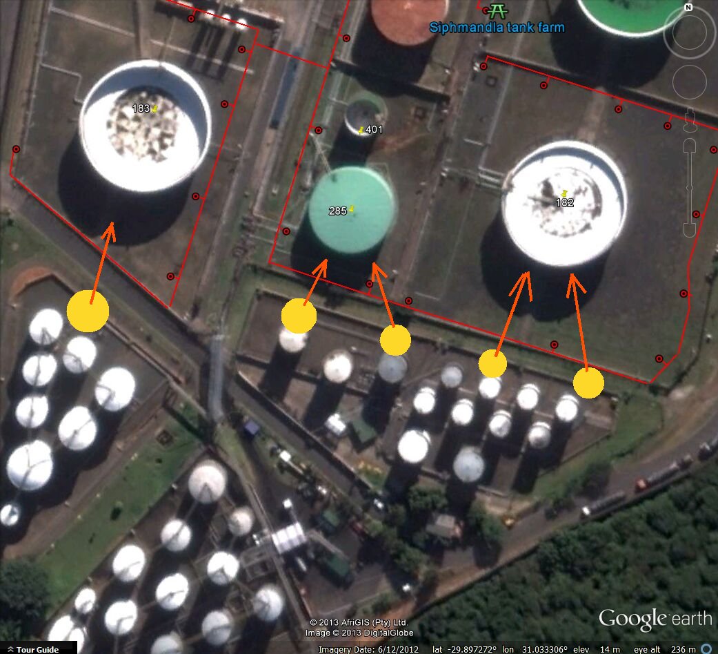
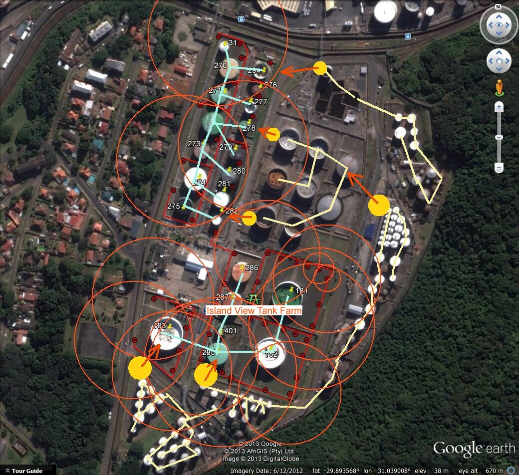
extending this reasoning it is possible to suggest that interference corrosion is being caused at the yellow spots shown in the following pictures.
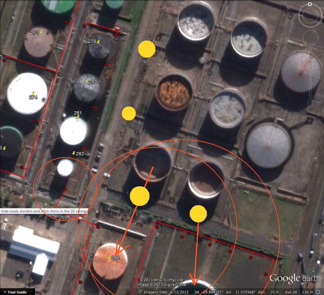
It can be seen that the least line of resistance through the earth is as shown by the red arrows and the yellow spots denote the likely places that the current leave the metal to travel in the earth.
Zooming out, we can see that the charges will also affect the electrical equilibrium of the metalic paths in the whole area. In order to define the corrosion problems that this is causing we must make arrangements with all other asset owners to carry out a combined data gathering project. This must be conducted by personel who understand that they are in fact making electrical measurments pertaining to an intergrated circuit and that these measurements must be related to a common potential for analysis. Traditional 'pipe-to-soil' voltage measurements cannot be computer analysed as the are potentials between to floating values.
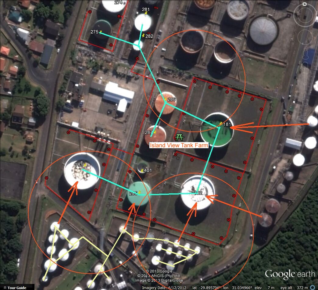
The red circles in this picture show the probable distribution of charges from the two TRU's
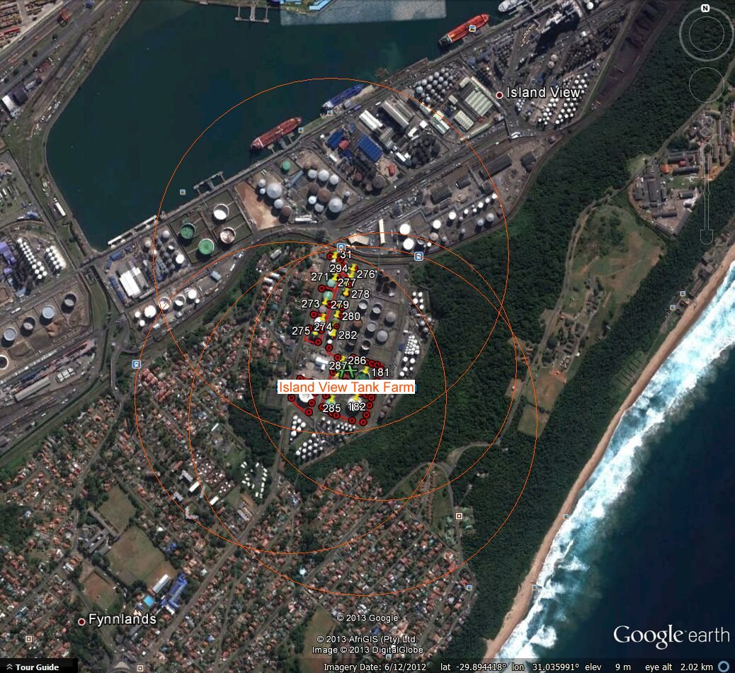
The blue lines show the negative side of our CP systems.
The yellow lines show the 'metalic blocks' that are probably not directly connected to our negative side and can be picking up charges from our system that are then discharging to ground and causing accelerated corrosion.
The red circles show the likely distribution of charges through the 'shells of resistance' described by many scientists and electrical engineers.
The yellow spots show the locations that shold be examined for active corrosion.

The red arrows show the direction that the charges are likely to take due to the 'least line of resistance (as described in Kirchoff's Laws)
Summary
The specified work has been carried out and the data shows that the system is funtioning successfully.
The fact that there have been no major corrosion failures to the tank bottoms shows that the original design is credible.
The refurbished system will have the same effect as the system that it has replaced but further investigation must be undertaken to confirm that the new system will not cause accelerated corrosion elsewhere in the tank farm and to 'foreign' plant and facilities in the area.
It is very important to understand that any addition, alteration or adjustment to any cathodic protection system changes the electrical equilibrium of all other cathodic protection systems and metalic structures, This is a natural law of science and is the basis of all electronics.